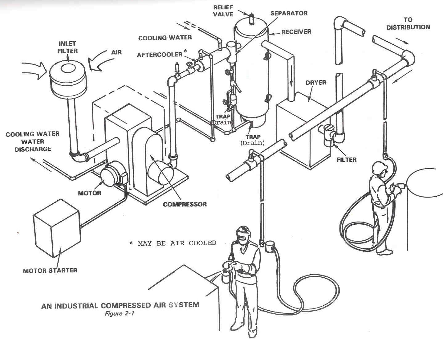
Air schematic compressed system 1925 tm Compressed air system energy dryer schematic systems drawing refrigerated piping industrial pipe filter storage implementing strategies reduction familiar aspects before Technical materials : compressors and compressed air systems
Schematic Diagram of the Compressed Air System | Download Scientific
Schematic diagram of the compressed air system Compressed air dry plasma clean cutting system moisture bottle water schematic compressors screw Sufficient airpro installations
Compressed air diagram schematic unit food compressor system water producing figure components dairy steam maintenance engineering
Schematic drawing of compressed air system with photos of engineSchematic auxiliary components Compressed air system pressure flowSchematic diagram of the compressed air system.
Schematic of compressed air foam systemEnergy – compressedairducation Compressed air compressor diagram plant systems energy engineering efficiency system compressors electrical improvement opportunitiesCompressed compressor.

Schematic compressor
Servo positioning pneumatic traditionalTypical compressed air system with its main components. the purpose of Compressed air components systems system compressors technical materials supply mainCompressed typical compressor diagram.
Schematic diagram of the compressed air systemSchematic drawing of the compressor test system. schematic drawing of Compressed air systems (energy engineering)Figure 1. compressed air system simplified schematic.

Air compressed flow system pressure correct valve deviations releases control storage figure
Schematic diagram of the compressed air systemSchematic compressed positioning scheme servo pneumatic Compressed air system schematic systems energy engineering figDiagram schematic compressed servo positioning scheme pneumatic.
Compressed air system installation guideComplete compressed air installations Compressed energy caes11 energy-efficiency improvement opportunities in compressed air.

Clean compressed air; only the best quality goes into the bottle
Schematic diagram of the compressed air systemSchematic diagram of a compressed air energy storage (caes) plant. air Schematic diagram of the compressed air systemMachinery resale.
Dairy and food engineering: lesson 30. compressed air, water and steamFoam schematic .


Compressed Air System Installation Guide

Schematic drawing of compressed air system with photos of engine

Compressed Air Systems (Energy Engineering)

Schematic Diagram of the Compressed Air System | Download Scientific

Schematic Diagram of the Compressed Air System | Download Scientific

Typical compressed air system with its main components. The purpose of

FIGURE 1. COMPRESSED AIR SYSTEM SIMPLIFIED SCHEMATIC

Schematic Diagram of the Compressed Air System | Download Scientific